
Most of my electronic projects end up using buck converters. I’ve bought a bunch, including some low functionality “set and forget” ones for leaving in projects.
This one is going on my 3D printer to power the Raspberry Pi which runs OctoPi.
I designed the box in the CAD system I use for work, I had a go with FreeCAD, it’s been ages since I last used it and I think I need to take a day or two to get used to it again. I use constrained sketches a lot in the work CAD system and I’ve always been pleased to see similar concepts in FreeCAD, but I didn’t get on with it at all this evening. So I went back to what I’m used to using.
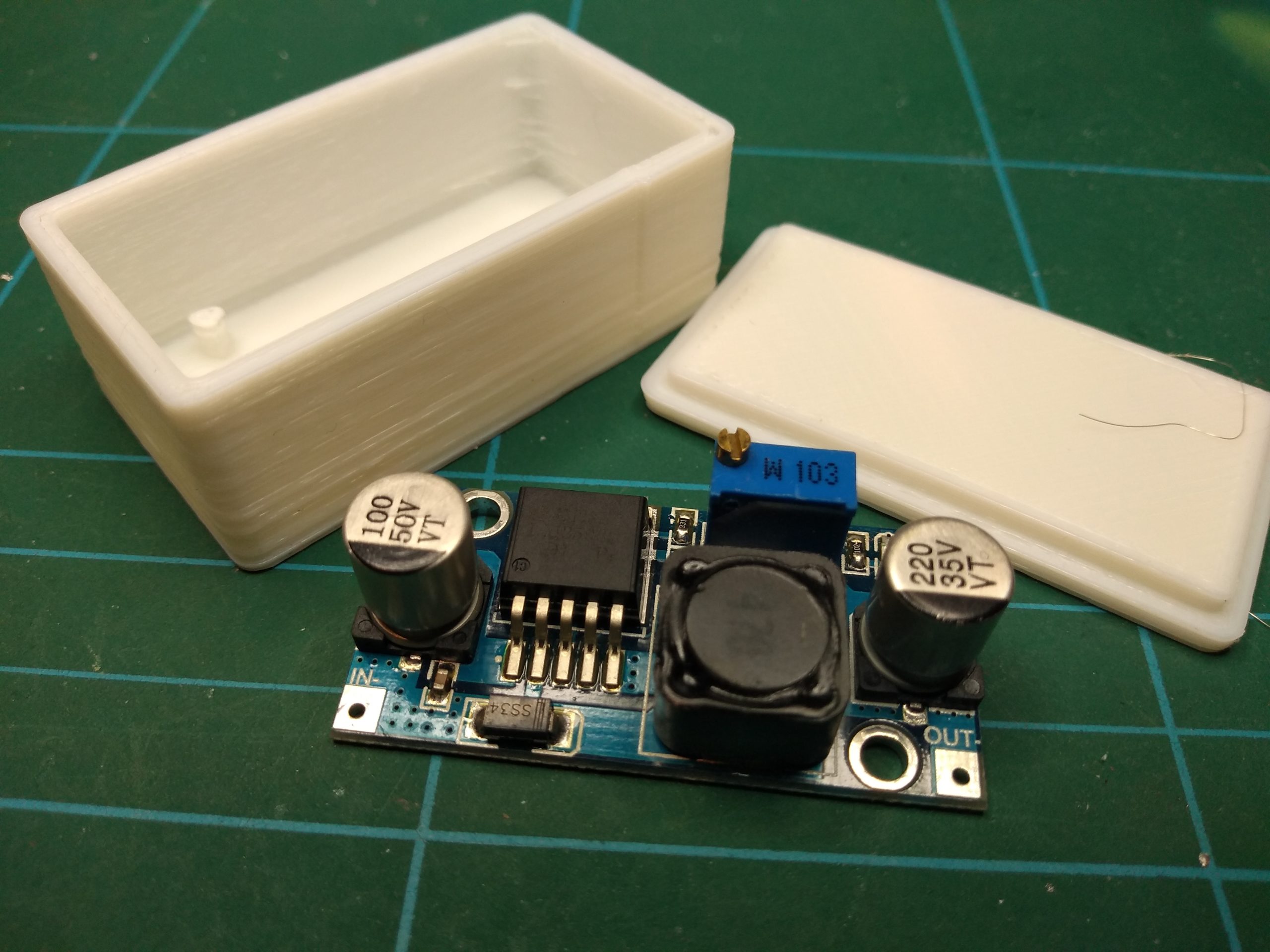
I modelled the PCB in it’s most basic form – thickness, holes, etc.
Then I drew a box around it, giving 1mm clearance. Around that I drew another box to give 2mm wall thickness.
I extruded that 2mm down from the datum plane and 17mm up from the datum plane.
Then I drew a box on the bottom which sealed one side. 2mm extrusion.
I used the mounting holes as pin locations, 5mm extrusion up from the base.
New part, sketch plane on the top of the box. Drew a rectangle and constrained it to the inside edges of my enclosure. Extruded down 2mm. Selected the top surface as the sketch plane and drew a rectangle which I constrained to the outside of the enclosure. Extruded up 2mm.
Job done. Saved to the server, exported as STL, ran through Slic3r and printed.
The top needed a bit of a shave, but in the end it fitted nicely.

If I was doing it again, I’d put the mounting pips on the lid, that way I’d be able to easily access the board. I’d also put some cable cutouts in the sides so the really tight press fit would grip the cables. I may re-do it, I may not.