Back in the mists of time, in the previous century, I bought a computer, an Amiga A4000/030
I brought it home the day that news of Kurt Cobain’s death hit the news, April 1994. It was an upgrade from my A500.
I used it for many things, lots of computer graphics stuff, lots of video. It got a new processor, it got an animation recorder card, it got several hard disks.
Then it died. The power supply wasn’t particularly strong to start with and I’d been pushing it a bit past where I should have. There was bitter, acrid smoke, and all the breakers in the house tripped. Catastrophic failure.
A PC AT style power supply was quickly pressed into service. The motherboard plugs cut off and an amiga 6 pin molex grafted on.
So “Dogfood” was born – christened when a friend remarked that all the giblets were hanging out, just like dogfood.
Ideally, I would have done a better job of PSU replacement. The top of the case didn’t fit any longer, so Dogfood spent a few years sat on a set of drawers underneath a worktop, facing backwards with all the ports showing, working hard but not as cherished as it should have been.
So let’s do something about that now.
The PC-AT power supply is old. It’s also too big for the case and will never fit in.
When I think of power supplies I usually think of ATX power supplies, but they don’t fit either. There are smaller form factor PSUs, so I googled about and found this document from Silverstone on power supply sizes.
ATX is too wide
So is ATX/PS3
However, SFX (aka MicroATX) at 125mm wide is the perfect width. It is also much shorter than the original PSU (which overcomes the tight space for CD drives) , but it is less tall than the original PSU so the internal hard disk drives will need some other method of support.
SFX it is. I bought this one because it was cheap (and so am I).
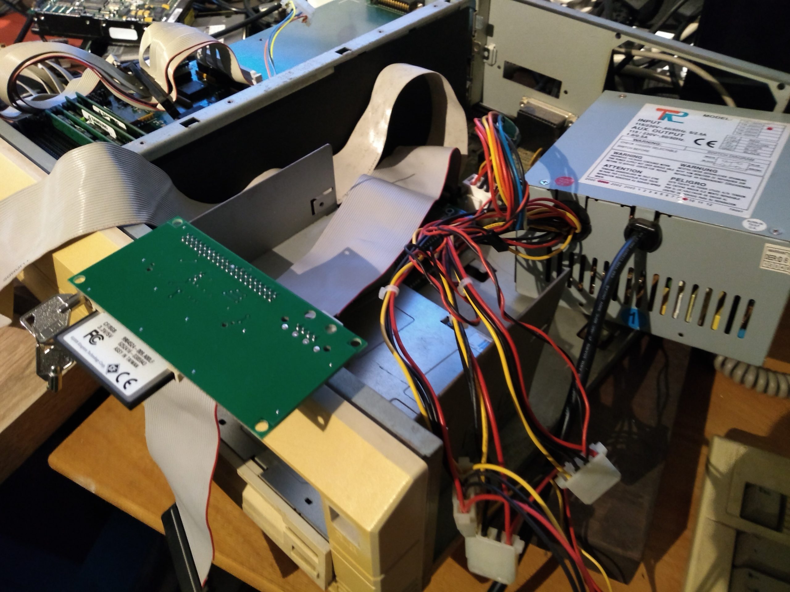
When it arrived, I had intended to pair it with an ATX to Amiga 4000 cable but once connected together there were an awful lot of surplus wires. I dove into the PSU, removed the 3.3v wires, connected the 3.3v sense (the brown wire) to the 3.3v pads, clipped out all the unneccesary cables and patched in the A4000 motherboard connector and the switch.

This haircut greatly reduced the amount of clutter. The new PSU looks tiny, but is nearly twice the power of the original PSU.
So, with the PSU prepared and tested I turned my attention to the case.
The first step was to get some card and make a fake replacement box. I wanted to cover the hole left by the larger Amiga PSU. I wanted to use the original mounting clips. I wanted a neat path to the motherboard power. I wanted to be able to position hard disks in the original place.
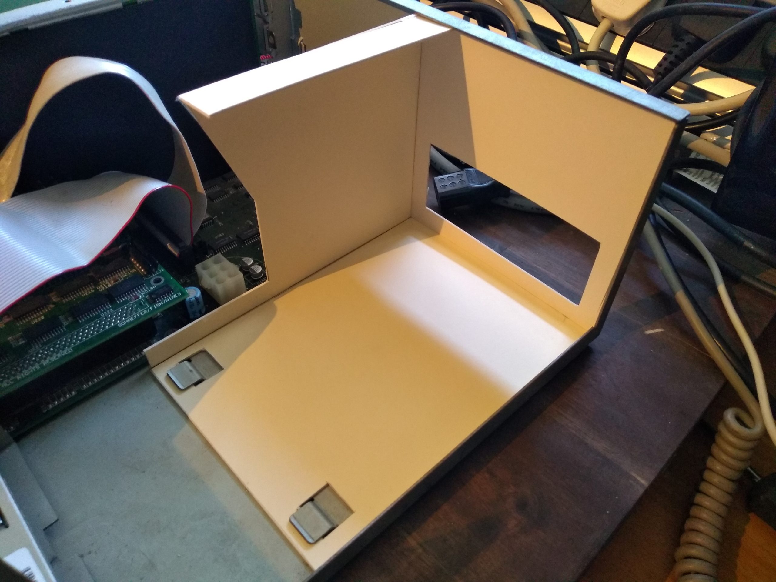
Mountboard mockup held together with sticky tape.

Doesn’t the new PSU look tiny. You can see the extent of the original. The path to the motherboard power connector is neat and there isn’t too much spare cable. There is also more room to get to the front drive bays, the clutter and tangled ribbon cables have always been a cooling issue in A4000s.
So, that’s what I want to make but how to actually make it.
I did consider folded sheet metal
I thought long and hard about this. In the end I decided that the radius of the folds that I could achieve would never match the superbly sharp corners on the power supply. I’d end up with the PSU floating in the air just above the base because of the corner radius.
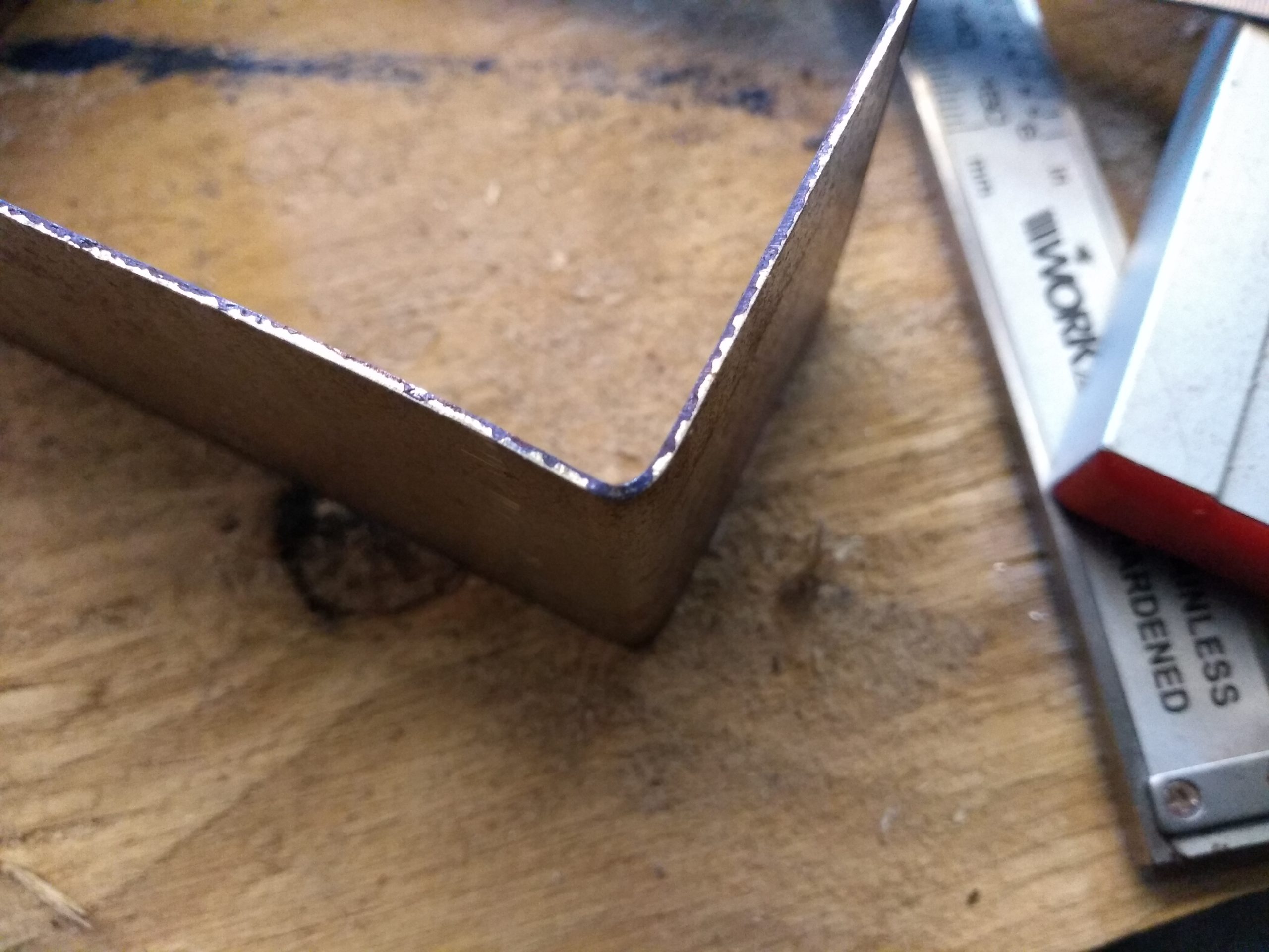
Eventually I decided to weld it together.

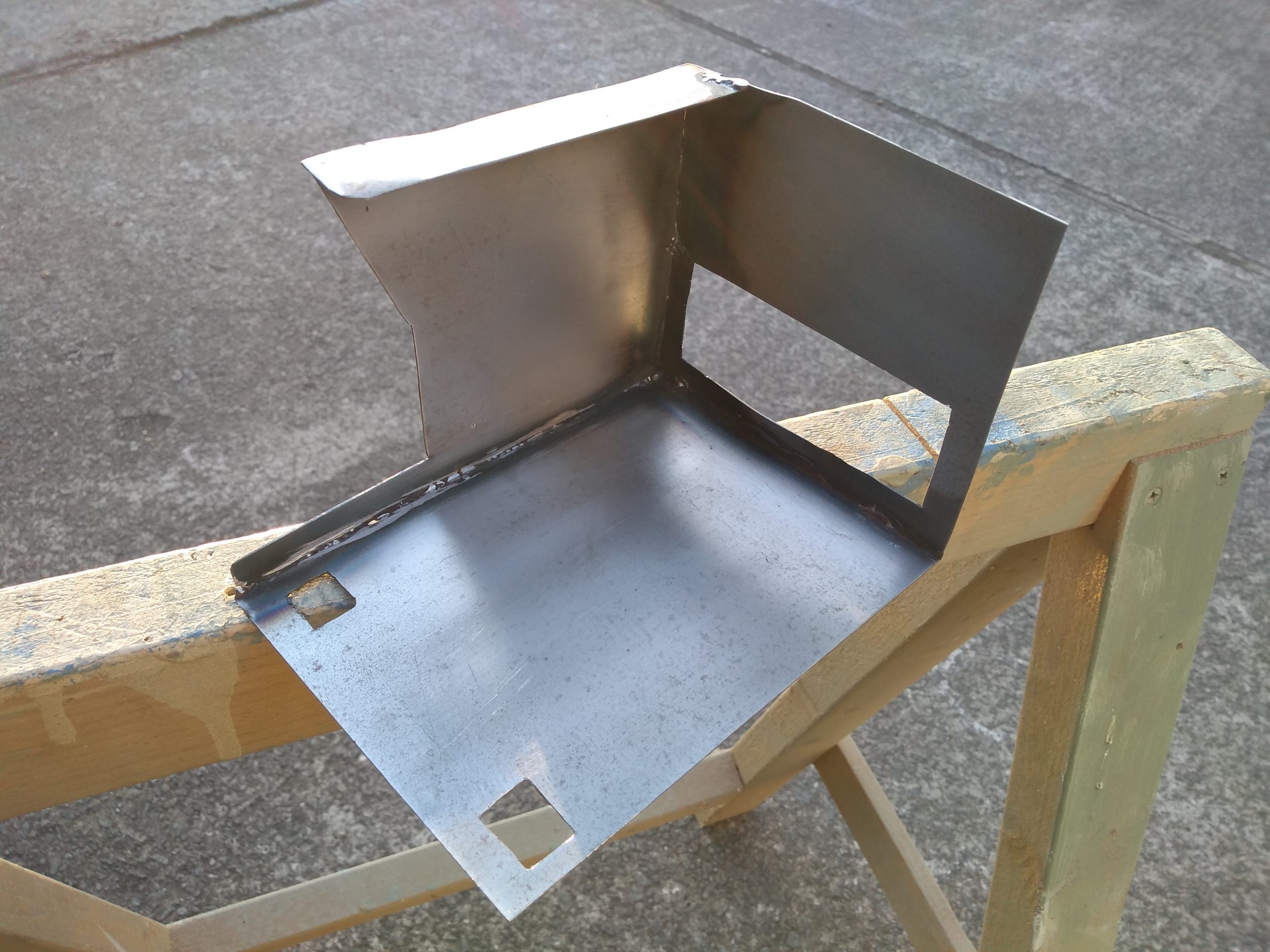
The resultant part came out OK… My metalwork isn’t brilliant so it is a little rough round the edges. My grinding is much better than my welding so it came out looking OK. I gave it a shot of etch primer to prevent rust and make it look similar to other case work.

I think that looks OK. I still need to drill mount holes for the hard drive cradle and to attach it to the back of the chassis, but overall I’m happy with it.
We will see how it gets on. I’d heard that dummy load resistors on the unused 3.3v rail might be necessary but it seems OK without.
I’m happy to be giving dogfood a bit of attention.