Williams Pinball Power Driver Board Rebuild Kit

I’ve decided to try and get all my pinball machines working reliably.

I’ve got…

  1. Star Trek: The next Generation – which has weak and wavering flippers.
  2. Dr Who – which has wires off the switch matrix connector and weak and wavering flippers.
  3. Judge Dredd – which suffers from not-quite-resetting, but being crashy.
  4. High Speed 2: The Getaway – which works fine, but the supercharger has been stronger.
  5. Bride Of Pinbot – which mostly works, but the General Illumination is a car-crash.

I’ve tried to diagnose the weak and wavering flipper issues. Initially with a flipper rebuild which helped a little, but only a little. I’ve reseated and cleaned connectors to the flipper driver board, might have helped a tiny bit. I’m now thinking that the power driver is struggling to supply power under load. The issues start on the second or third game, so it is a warming up problem. My assumption is that I’ll need to replace the relevant capacitor and maybe it’ll be a good fix.

The not-quite-resetting issue on Judge Dredd is probably the same thing. It’ll run for a couple of minutes then things start to die. Sound, then DMD, then it just locks up. My guess would be that a 5v fix is called for.

Getaway is reliable, but in the past I’ve had the supercharger running so damn fast that it shakes the whole machine when it flings the ball round the loop. It’s barely making it right now. My guess is that I might have an intermittent opto problem, or maybe that it just needs cleaning or tuning.

Bride of Pinbot has been butchered to hell and back. A couple of years ago I tried to tackle the dodgy General Illumination connectors. They had been badly burned and someone had soldered wires on the back of the power driver (poorly) and connected up screw terminal blocks. They shouldn’t have.

So, my diagnosis is that all 5 of my machines are coming to a point in their life where the power driver circuitry isn’t very reliable. I’ve got a replacement power driver board – a Rottendog board so I’ve got something “known good” to test and see if it resolves issues with each machine.

Rottendog Power Driver Board

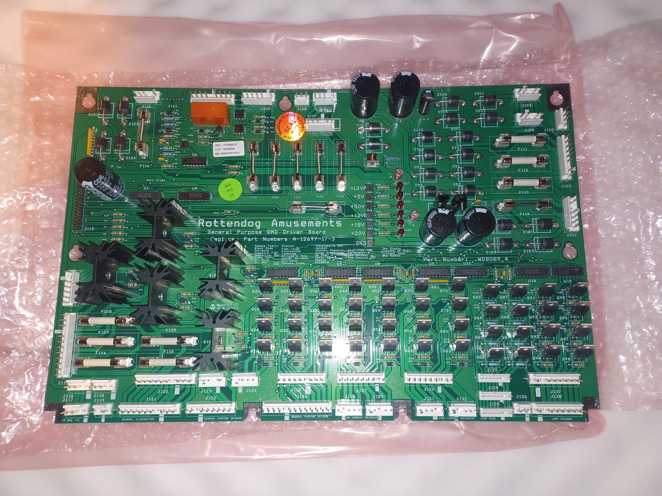
This also means that I can pull a board, work on it on the bench, knowing that if I get stuck, get distracted and have to put the board away for a while (turning into weeks, months, years) then I’ll still have a working and complete machine, albeit not a numbers matching one. When I’ve finished repairing all the machines I’ll either put the Rottendog aside for future fixes or maybe replace the driver board in The Machine: Bride of Pinbot.

I’ve bought a power driver board rebuild kit – these are generally frowned upon. Replacing a large number of probably good components (aka “Shotgunning”) can damage boards, particularly the through hole grommets when removing the snap-in capacitors. Traces can also get lifted, etc. I know this because I did a really poor job of fixing 5V on my Dr Who some years ago when I attempted my first pinball repair.

My view is that many of these components are well past their end of life (30+ years) and I’m starting to see the same faults on machines of a similar age. Replacing the “failed or about to fail” components means I am less likely to have to pull boards in the future.

My repair process will be…

  1. Label up the wiring harness, particularly the connectors to the driver board.
  2. Remove original Williams board and replace with Rottendog.
  3. Run all diagnostics. Solenoids, Flashers, Lamps, GI, Switches, etc. Do quick fixes.
  4. Play the game for a few hours.
  5. Run all diagnostics again.
  6. Shotgun the Williams driver board. Caps, Bridges, Connectors.
  7. Replace Rottendog with the Williams driver board.
  8. Run all diagnostics again.
  9. Play the game for a few hours.
  10. Make notes of any more fixes required and move on.

As shotgunning the boards is seen as a “Bad Thing”, I’ve only been able to find one rebuild kit.
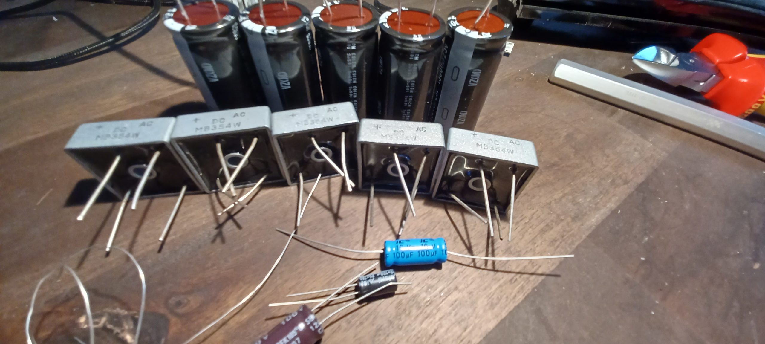
It comprises…

  1. Bridge Rectifiers (Marked MB354W) (x5)
  2. 15,000 uF 25 Capictors VZ(M)165 degrees C H2103 22.25mm dia 50.77long 10mm between leads (x5)
  3. Axial Capacitor 16v 100uFBPAM G85 degrees C20 8.2mm dia 19.54 long (x1)
  4. 100 uF 100v SEK 105 degrees C 12/07 C3 10.2mm dia 20.53mm long (x1)
  5. 25v 100uF WH105 degrees C 2149WPET6.5mm dia 11.3mm long (x1)
  6. A piece of soft copper wire to replace through hole gromments when you fuck them up.

I think that the 15,000 uF capacitors look longer and thinner than originals. I’ll measure up and may order the right size ones, but avoid the clip in legs.

I’ll try and produce updates of how the machines are getting on as I get them all fixed.

I’ve set myself a deadline of “Christmas” to have them all working well again. Experience shows that this will be an expensive and time consuming effort…

Automatic Opening Kitchen Bin Repair

Some time ago I bought an “Automatic Opening Kitchen Bin” from Amazon.

I would provide a link, but I don’t think they stock the particular one I bought, probably because it is unreliable. The idea is that you wave your hand over the top of the bin and it magically opens. It then closes a few seconds later. Mine doesn’t.

Turning the top over, you can see it is secured with 10 screws.

These come out easily with a number one Phillips screwdriver.

At the back, there is a motor, battery box and on-off switch.

At the front there is the sensor, brains and motor driver board.

From the video at the start of this post, you can see that the sensor works. It does try to open the bin. It doesn’t fully open it, it kinda does an open/close movement.

The bin is then held slightly open for a reasonable amount of time, then it closes in a satisfyingly purposeful manner.

So, to summarise…

  1. The sensor works fine.
  2. The open function doesn’t work well at all.
  3. The timer works fine.
  4. The close function works perfectly.

So my bet is that the motor driver part is faulty. Let’s have a closer look at that board.

Wow! I was not expecting such a complex board for such a simple job.

You can see the IC in the centre of the board, I guess that is some sort of microcontroller handling the timing and sending open/close signals.

You can see the four transistors on the left hand side of the board. My guess is that these are forming a H-Bridge motor driver circuit.

They are labelled

  1. Q2 – SS8550 flat face to the right.
  2. Q3 – SS0850 flat face to the left.
  3. Q4 – SS8550 flat face to the right
  4. Q5 – SS8050 flat face to the left.

SS8550 is a PNP transistor

SS8050 is it’s NPN sister.

There is a description of an H-Bridge on “Learning about electronics” It is helpful. Given that I’ve found 4 transistors of the correct types to form a H-Bridge, I’m going to stop my investigations there and just make the wild assumption that one of these has died. I’ll replace them all and see if it works afterwards.

I pulled out the transitors (using my fabulous desoldering “moo” gun) and tested them. All but one tested OK, but one SS8050 showed…

Which doesn’t look at all “transistory” I think it (and it’s sisters) need replacing. Fortunately I’ve just bought a big box of transistors.

So I installed new replacements, put everything back together and gave it a quick test.

No difference, still the same slow open and half close.

Maybe it’s the motor. The wiring round there is a bit of a mess, there is a rather hacked together mess around an opto pair with a flag wheel. I pulled the motor out and checked how it engaged with the arm that opens the bin lid. All looked clean, well lubricated and no signs of wear.

Then I did the most obvious thing – the thing I should have done first… I changed the batteries.

Lesson learned. Check the basics first.

A4000 Replacement Power Supply

Back in the mists of time, in the previous century, I bought a computer, an Amiga A4000/030

I brought it home the day that news of Kurt Cobain’s death hit the news, April 1994. It was an upgrade from my A500.

I used it for many things, lots of computer graphics stuff, lots of video. It got a new processor, it got an animation recorder card, it got several hard disks.

Then it died. The power supply wasn’t particularly strong to start with and I’d been pushing it a bit past where I should have. There was bitter, acrid smoke, and all the breakers in the house tripped. Catastrophic failure.

A PC AT style power supply was quickly pressed into service. The motherboard plugs cut off and an amiga 6 pin molex grafted on.

So “Dogfood” was born – christened when a friend remarked that all the giblets were hanging out, just like dogfood.

Dogfood – Looking somewhat better organised than usual.

Ideally, I would have done a better job of PSU replacement. The top of the case didn’t fit any longer, so Dogfood spent a few years sat on a set of drawers underneath a worktop, facing backwards with all the ports showing, working hard but not as cherished as it should have been.

So let’s do something about that now.

Continue reading

External Amiga Floppy conversion into Gotek

Back in 1992 I bought an external floppy drive for my Amiga A500 Plus.

This completely transformed the way I used the machine and was such an improvement right up until I bought a GVP Impact HD8+ hard drive – a SCSI Quantum LPS52 drive which gave a mind blowing 52 Megabytes of storage.

I’m slowly working through my collection of Amiga stuff and getting things tested and working. One of the godsends has been a Gotek floppy disk emulator. It allows you to download .adf disk images onto a USB drive and emulates a floppy drive. It is great for getting things set up and installing hardware drivers etc.

So, I thought I would convert the slightly unreliable 30 year old floppy into an external Gotek drive.

Looks like it was the 725th made in March 1992

Opening the Cumana CAX354 shows a citizen floppy mechanism and a small board to allow pass through and disable switch.

30 years old and still so shiny!
Continue reading

Amiga Bits

I’m selling some old computer stuff. I’ve included pictures here to avoid cluttering up the for-sale listing. You can click on the pictures for a full resolution version. I’ve used flash to try and get a reflection off the surfaces so you can see the texture easier. If anything is unclear drop me a line and I’ll take pictures under natural light tomorrow.

Cyberstorm PPC

Output from WhichAmiga beta
Front side of the board

Back side of the board

I’ve been asked for some more info, so…

WhichAmiga and Showconfig
PPC board running voxel demo and showinfo

This one is a bit crap – I don’t have a graphics card in this machine so it is having to run in 8 colour workbench… It does however show that the ppc is there and working. It is a 233Mhz, and the voxelspace demo takes very little of the cpu power.

Cyberstorm mk3

CyberVision PPC – fits either CS-PPC or CV-PPC

Cyberstorm 060

SCSI Module for Cyberstorm Mk2

Hinge Design

Handmade Hinges

My hot and cold water tanks are accessed through a small door.

This door has never closed properly and opens into the tank space, making it difficult to move around. I’m having some work done in there, so though it a good idea to improve access, hoover up all the dust and clean out the debris left when things were installed several decades ago.

As is usual, this fairly trivial task becomes more complex. However, I found the hinges to the access door rather interesting.

Continue reading