I’ve decided to try and get all my pinball machines working reliably.
I’ve got…
- Star Trek: The next Generation – which has weak and wavering flippers.
- Dr Who – which has wires off the switch matrix connector and weak and wavering flippers.
- Judge Dredd – which suffers from not-quite-resetting, but being crashy.
- High Speed 2: The Getaway – which works fine, but the supercharger has been stronger.
- Bride Of Pinbot – which mostly works, but the General Illumination is a car-crash.
I’ve tried to diagnose the weak and wavering flipper issues. Initially with a flipper rebuild which helped a little, but only a little. I’ve reseated and cleaned connectors to the flipper driver board, might have helped a tiny bit. I’m now thinking that the power driver is struggling to supply power under load. The issues start on the second or third game, so it is a warming up problem. My assumption is that I’ll need to replace the relevant capacitor and maybe it’ll be a good fix.
The not-quite-resetting issue on Judge Dredd is probably the same thing. It’ll run for a couple of minutes then things start to die. Sound, then DMD, then it just locks up. My guess would be that a 5v fix is called for.
Getaway is reliable, but in the past I’ve had the supercharger running so damn fast that it shakes the whole machine when it flings the ball round the loop. It’s barely making it right now. My guess is that I might have an intermittent opto problem, or maybe that it just needs cleaning or tuning.
Bride of Pinbot has been butchered to hell and back. A couple of years ago I tried to tackle the dodgy General Illumination connectors. They had been badly burned and someone had soldered wires on the back of the power driver (poorly) and connected up screw terminal blocks. They shouldn’t have.
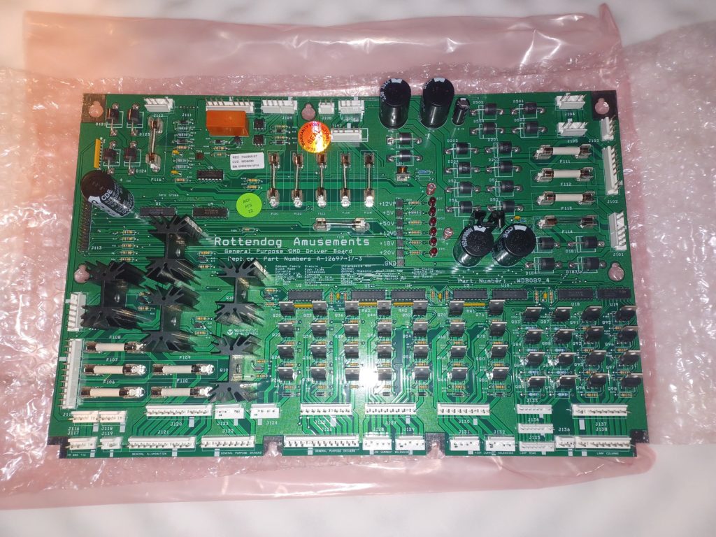
So, my diagnosis is that all 5 of my machines are coming to a point in their life where the power driver circuitry isn’t very reliable. I’ve got a replacement power driver board – a Rottendog board so I’ve got something “known good” to test and see if it resolves issues with each machine.

This also means that I can pull a board, work on it on the bench, knowing that if I get stuck, get distracted and have to put the board away for a while (turning into weeks, months, years) then I’ll still have a working and complete machine, albeit not a numbers matching one. When I’ve finished repairing all the machines I’ll either put the Rottendog aside for future fixes or maybe replace the driver board in The Machine: Bride of Pinbot.
I’ve bought a power driver board rebuild kit – these are generally frowned upon. Replacing a large number of probably good components (aka “Shotgunning”) can damage boards, particularly the through hole grommets when removing the snap-in capacitors. Traces can also get lifted, etc. I know this because I did a really poor job of fixing 5V on my Dr Who some years ago when I attempted my first pinball repair.
My view is that many of these components are well past their end of life (30+ years) and I’m starting to see the same faults on machines of a similar age. Replacing the “failed or about to fail” components means I am less likely to have to pull boards in the future.
My repair process will be…
- Label up the wiring harness, particularly the connectors to the driver board.
- Remove original Williams board and replace with Rottendog.
- Run all diagnostics. Solenoids, Flashers, Lamps, GI, Switches, etc. Do quick fixes.
- Play the game for a few hours.
- Run all diagnostics again.
- Shotgun the Williams driver board. Caps, Bridges, Connectors.
- Replace Rottendog with the Williams driver board.
- Run all diagnostics again.
- Play the game for a few hours.
- Make notes of any more fixes required and move on.
As shotgunning the boards is seen as a “Bad Thing”, I’ve only been able to find one rebuild kit.

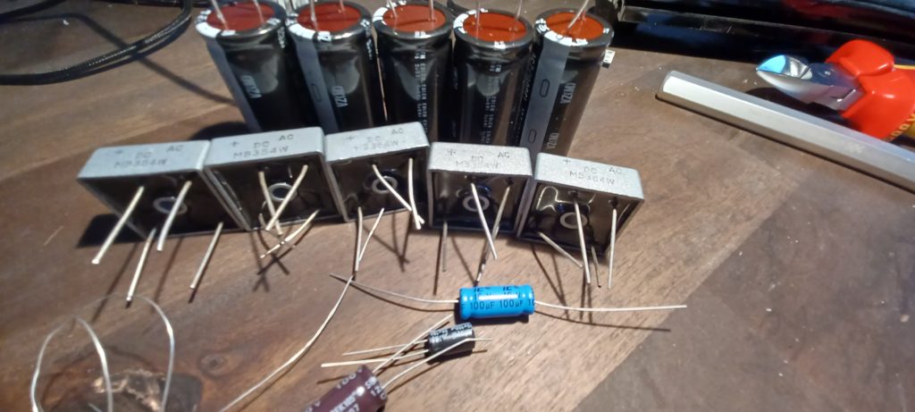
It comprises…
- Bridge Rectifiers (Marked MB354W) (x5)
- 15,000 uF 25 Capictors VZ(M)165 degrees C H2103 22.25mm dia 50.77long 10mm between leads (x5)
- Axial Capacitor 16v 100uFBPAM G85 degrees C20 8.2mm dia 19.54 long (x1)
- 100 uF 100v SEK 105 degrees C 12/07 C3 10.2mm dia 20.53mm long (x1)
- 25v 100uF WH105 degrees C 2149WPET6.5mm dia 11.3mm long (x1)
- A piece of soft copper wire to replace through hole gromments when you fuck them up.
I think that the 15,000 uF capacitors look longer and thinner than originals. I’ll measure up and may order the right size ones, but avoid the clip in legs.
I’ll try and produce updates of how the machines are getting on as I get them all fixed.
I’ve set myself a deadline of “Christmas” to have them all working well again. Experience shows that this will be an expensive and time consuming effort…

Hi, where did you get the rebuild kit?